Mechanical Arm Teaching Unveiled: From Hardware Authentication to Camera Setup, Advantech Makes It Easy!
·loading
Author
Advantech ESS
Table of Contents
Table of Contents
Introduction: The First Step in Robot Teaching—Never Overlook the Basics!
#
Have you ever wondered where to start when teaching a robotic arm new movements? The answer is simple—let it recognize you first! On Advantech’s Physical AI platform, every magical process of robot teaching, recording, training, and inference starts with hardware authentication and calibration. It’s like making sure your ruler is accurate before measuring—no matter how diligent you are, you’ll end up with a beautiful but wrong answer if you skip this step!
In this article, we’ll break down our latest breakthroughs in robotic arm teaching, from hardware authentication and Leader-Follower setup to camera perspective configuration. Whether you’re an AE, a salesperson, or a newcomer, you’ll find Advantech’s innovation and expertise easy to understand!
Background & Technical Overview: Robotic Arm Platforms Differ—Why Take These Steps?
#
Two Major Robotic Arm Platforms: Which Hardware Do You Have?
#
Advantech Physical AI currently supports two types of robotic arms:
Item
OpenMANIPULATOR-X
SO-101
Source
ROBOTIS Educational/Research Model
LeRobot Open-Source, Cost-Effective Design
Motor
Dynamixel Smart Motor
Feetech Servo
Connection
OpenRB-150 Controller Board
One USB Each for Leader/Follower
Auto-Detection
Yes
No (Manual Calibration Required)
Travel Calibration
Not Required
Required (Both Leader and Follower)
Typical Use
Education, Research, Stable Environments
Budget-Conscious, Teaching, Rapid Prototyping
In short, OpenMANIPULATOR-X is ideal for stable experiments and automated setup; SO-101 offers flexible adjustments and low-cost implementation but requires an extra manual calibration step. This flexibility is how Advantech addresses different market needs!
Leader-Follower Architecture: The Robotic Version of Master Teaching Apprentice
#
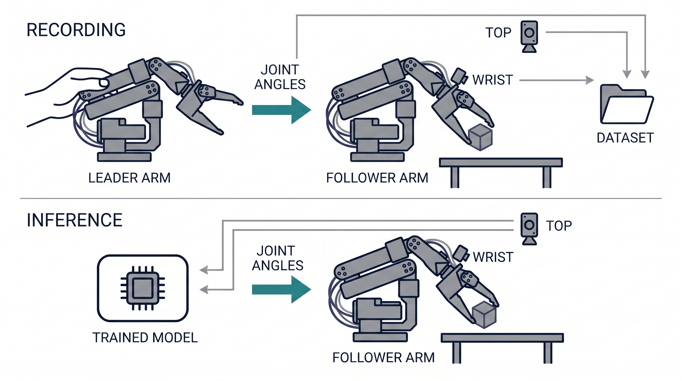
We adopt the Leader-Follower teleoperation approach, similar to a master guiding an apprentice:
Leader Arm (Operator Side): Driven by human hand to record movements
Follower Arm (Executor Side): Instantly replicates Leader’s movements to complete tasks
Both arms’ trajectories and images are recorded synchronously during teaching. After training, the model replaces the Leader, enabling the Follower to perform new skills. This design not only makes teaching more intuitive but also ensures precise and accurate data collection.
Implementation & Key Findings: Complete Guide to Hardware Authentication, Plug-and-Play Detection, and Calibration
#
1. How Does the System Recognize Your Robotic Arm?
#
When the platform starts, it automatically scans the host’s serial devices:
Finds OpenRB-150 controller board → Identifies as OpenMANIPULATOR-X
Not found → Defaults to SO-101
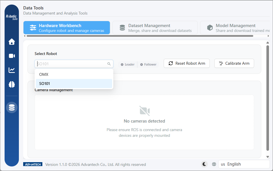
If you connect both types of hardware or the auto-detection is incorrect, simply go to “Data Tools → Hardware Workbench → Select Robot” to manually specify the model and click “Save Settings.” All hardware operations are done on this page—bookmark it for easy access!
Tip: After switching robot models, be sure to save your settings, or the calibration button will remain disabled. This fail-safe protects your hardware!
2. SO-101 Plug-and-Play Detection: Identify Leader and Follower by “Disappearance”
#
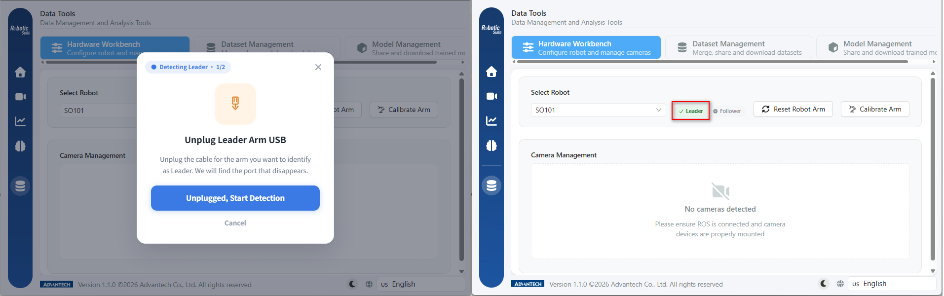
The two SO-101 arms connect via standard USB, making them indistinguishable to the system. Traditionally, you had to manually check device paths and edit config files. Advantech now turns this into a guided wizard:
Steps:
Check Connections: Plug both USB cables into the host
Guided Removal: Unplug the USB you want to assign as the Leader
Detection: The system compares before-and-after states and identifies the missing device
Auto-Fill Result: The correct path is written directly to the settings field—no manual copy-paste needed
Repeat for Follower: Perform the same steps to complete both identifications
Remember to plug both arms back into the host after identification, or subsequent calibration will fail!
What if you unplug the wrong device?
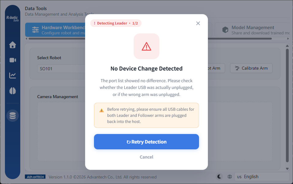
The system faithfully records whichever USB disappears; roles will be swapped, and you’ll notice during recording. Just rerun the process to overwrite the setting—no need to clear it manually. If you unplug nothing or a different device, the system clearly prompts: “No difference detected in port list.” Please reinsert the USB and try again.
OpenMANIPULATOR-X does not require plug-and-play identification—just click “Detect and Connect,” and the system will automatically reset and reconnect the arm.
3. Six-Motor Range Calibration: The Key to Precise Operation
#
Applicable to SO-101; the “Arm Calibration” button appears only when SO-101 is selected.
Why is calibration necessary?
Servos report raw tick values, not angles. To convert these into meaningful angles, the system must know the actual operational range of each motor on the arm. This depends on assembly details and varies per arm, making automated calibration impossible!
Calibration Procedure:
Prepare Position: Move the arm to a safe area, ensuring all joints can move freely (clear the workspace)
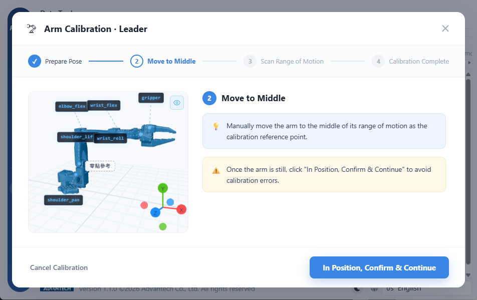
Move to Center: Manually position the arm at the center of its range, release, and wait for it to stabilize before sampling
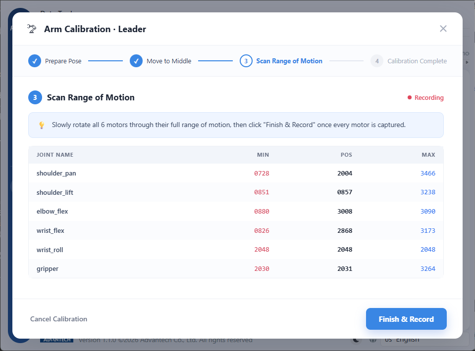
Scan Range: Slowly rotate all six motors to both ends; the system displays min/max/current values in real-time. Be sure to operate all motors through their full range!
Complete Calibration: The system writes calibration data after verifying all six joints have reasonable ranges; then calibrate the second arm
Common Mistakes & Consequences:
Action
Consequence
Moving too fast
Range shrinks, endpoints are skipped
Only partial rotation
Arm cannot reach some poses
Skipping gripper
Grasping actions fail
Hitting obstacles
False endpoints recorded, potential servo damage
“Slow” isn’t just polite—it’s precise! “To both ends” means until resistance is met or the mechanism stops.
Canceling Midway: If you close the wizard or cancel, the system will not save any partial or faulty settings—you can safely restart.
Terminology Tip: “Assist Offset Calculation” vs. “Arm Calibration”
Assist offset calculation aligns the virtual Follower with the physical Leader, while calibration aligns the real arm’s readings with reality. Ignore assist offset during hardware setup!
4. Camera Connection & Perspective Setup: Ensuring Data Quality
#
The platform’s vision system is open—any camera outputting standard images can be integrated, including USB webcams and Intel RealSense depth cameras, regardless of brand. Data quality depends on camera perspective, not specs—a well-placed standard camera beats a mispositioned high-end industrial camera!
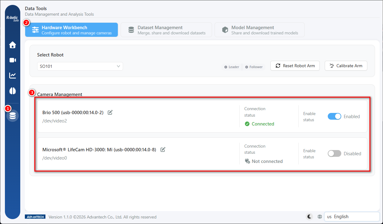
Manage at: Data Tools → Hardware Workbench → Camera Management
Connection Status: Connected / Error / Not Connected
Enable Toggle: Disabled cameras are excluded from datasets
Name Editing: Recommend “Wrist” and “Top” views
Recommended Perspective
Purpose
Wrist
Captures detail of gripper-object interactions
Top
Provides an overview of the work area
Important: The platform does not auto-name cameras—be sure to edit names to match actual placement!
This is the only way to distinguish multiple cameras and the only clue for future dataset reviews.
📷 Camera Management List
Must show: At least two cameras, one enabled and one disabled, connection status, and name edit pencil icon
If “No cameras detected” appears, check ROS connection and device mounting. This is a common issue with containerized deployment.
Minimum Requirement: Enable both Wrist and Top views—both are essential!
Camera configuration is closely tied to data quality; more in-depth discussions coming soon—stay tuned!
Results & Applications: Hardware Readiness Check for Smoother Processes
#
Before entering recording, simulation, or inference pages, the platform performs a hardware readiness check—a “preemptive interception,” not a “post-error alert.” You’ll receive feedback before investing time, improving efficiency and accuracy.
Page
Camera
Leader Arm
Follower Arm
Record /record
Required
Required
Required
Simulate /simulate
Required
Required
Not Checked
Inference /inference
Required
Not Checked
Required
Recording requires a human to operate the Leader while the Follower mirrors the movement; Simulation needs only the physical Leader; Inference has the model replace the Leader. Cameras are essential in all three scenarios—without image input, the model cannot interpret the world!
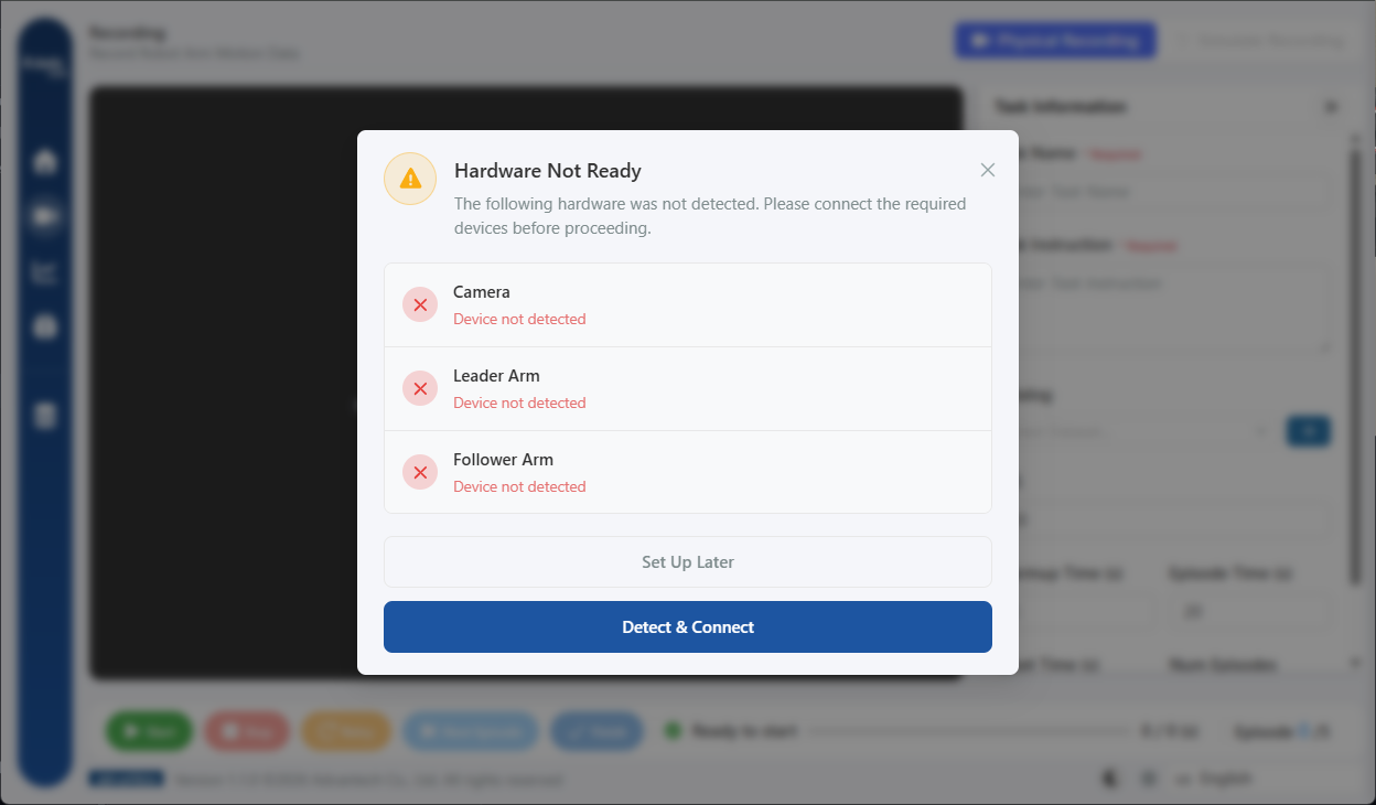
A popup lists all undetected items, offering “Detect and Connect” or “Set Up Later”—it’s not a hard block; you can still enter the page, but operations may fail.
📷 Hardware Not Ready Popup
Must show: missing items list, “Detect and Connect” and “Set Up Later” buttons at the bottom
Startup Checklist: All Set for a Smooth Recording Session
#
General Items
Robotic arms and cameras are connected to the host and powered on
Platform’s displayed model matches the actual hardware and settings are saved
Wrist and Top cameras are connected and enabled
Camera names match their actual positions
SO-101 Specific
Plug-and-play identification complete, ports assigned, USB reconnected to host
Follower responds in sync when Leader is moved (roles not reversed)
Both Leader and Follower badges show “Calibrated”
Calibration table shows reasonable ranges for all six joints (including gripper)
Final Verification
No hardware readiness warning popup when entering the recording page
Once you’ve completed these checks, your robotic arm is officially ready for its first teaching demo!
Hardware integration and calibration are the only steps in the Physical AI workflow that can’t be replaced by software. Advantech turns tedious terminal operations into guided wizards, auto-fills settings, and proactively intercepts errors—letting you see progress, easily retry mistakes, and complete each step with confidence.
The good news: this is a one-time task. Calibration results are saved; you won’t need to repeat them unless hardware is changed or reassembled. What once required trial-and-error by experienced users can now be accomplished by following platform prompts and the step-by-step checklist—making the recording process simple.
Advantech continues to advance automation and robot teaching, with more intelligent models, camera configurations, and task strategies coming soon—making robot teaching easier, more precise, and more enjoyable!
Once your hardware is ready, the next step is to choose a task strategy model—stay tuned for our in-depth guide!
Physical AI – Making robot teaching easy, making automation possible.